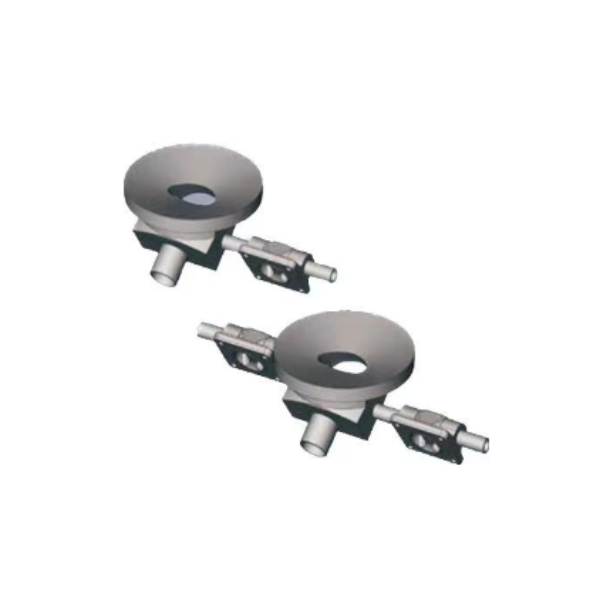
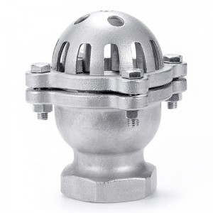
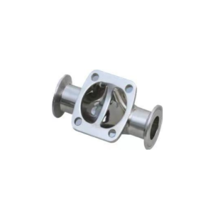
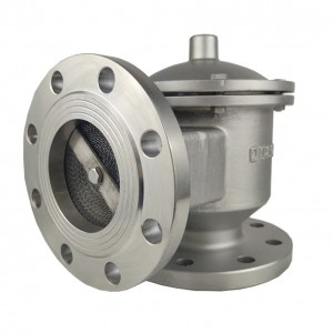
B600 GMP/SAP Valve Structure
Instructions for Use
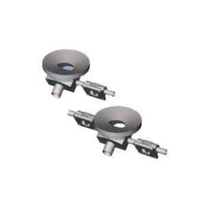
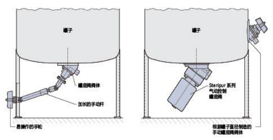
The tank bottom valve is welded at the bottom of the container, so as to achieve the best effect of emptying, cleaning and disinfection. In addition, the working medium can be well mixed according to the various technological requirements in the operation process. It is important that the sealing ridge of the tank bottom valve is already as close as possible to the bottom wall of the tank so as to achieve zero dead space effect.
Features
——The structure is compact, which can ensure the installation in a small space.
——No dead angle, can be automatically emptied. Body machined from one piece of material (no welded construction).
——Suitable for CIP and SIP processes, can be sterilized at high temperature, the surface of the valve body can be mechanically polished or electropolished according to requirements, and the precision can reach 0.25um.
——The structure is ideal both in terms of flow rate and process requirements, and there will be no turbulent flow during emptying process.
——All current international standard interfaces can be provided, such as welded joints, clamped joints or threaded joints, etc.
——The valve body material is 1.4435/316L stainless steel, of course, other alloys can also be used according to customer requirements.
——Tank bottom valve body can be equipped with hand wheel, pneumatic head or electric head.
——The welding ring design is adopted to reduce the difficulty of welding the bottom of the tank.
Surface Finish
Modern, well-designed workplaces and well-trained professionals provide a guarantee for high-quality processing of valve body surfaces. Different usage requirements can be achieved by grinding, polishing, electropolishing or electrolysis. Surface finish from 6.3m to 0.25m.
|
Valve Surface Finish Grade ( DIN4768 Standard) |
Code |
|
|
Ra≤0.6m |
The inner and outer surfaces are mechanically polished, and the outer surface is sandblasted with glass beads |
1534 |
|
Ra≤0.6m |
Electropolishing of inner and outer surfaces |
1535 |
|
Ra≤0.4m |
The inner and outer surfaces are mechanically polished, and the outer surface is sandblasted with glass beads |
1536 |
|
Ra≤0.4m |
Electropolishing of inner and outer surfaces |
1537 |
|
Ra≤0.25m |
The inner and outer surfaces are mechanically polished, and the outer surface is sandblasted with glass beads |
1538 |
|
Ra≤0.25m |
Electropolishing of inner and outer surfaces |
1539 |
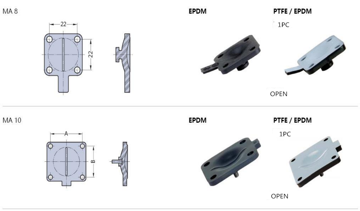
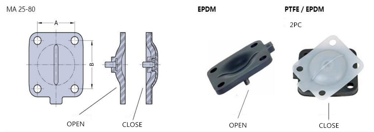
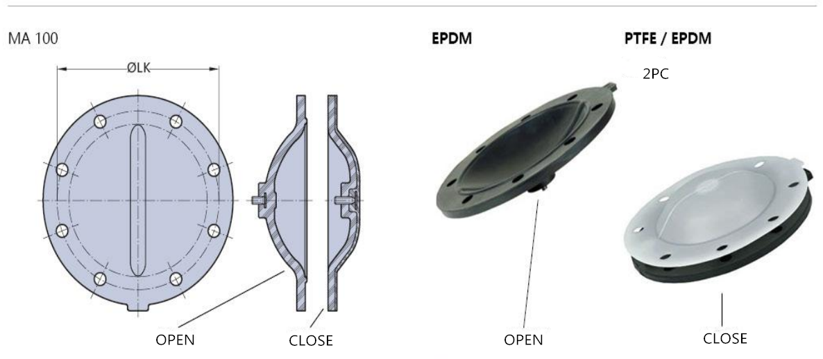
Diaphragms for Pharmaceutical,Food and Biotech
|
Diaphragm size |
Material |
FDA |
Fluid Medium |
High Temperature Steam Sterilization |
|
FPDM |
177.2600 |
90<C |
150℃/40min |
|
|
PTFE/EPDM |
177.1550/21 |
90<C |
150℃/40min |
|
|
EPDM |
177.2600 |
90<C |
130℃/40min |
|
|
PTFE/EPDM |
177.1550/21 |
90<C |
150℃/40min |
|
|
PTFE/EPDM |
177.1550/21 |
90<C |
150℃/60min |
|
|
PTFE |
177.1550/21 |
90<C |
160℃/60min |
|
|
EPDM |
177.2600 |
90<C |
130℃/40min |
Diaphragms
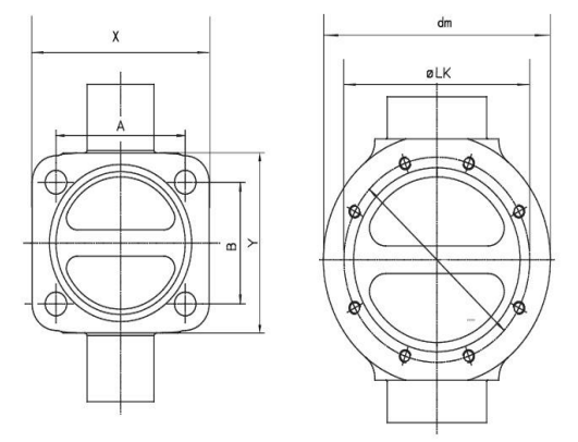
|
Valve Model |
MA |
ISO |
ASME-BPE |
A |
B |
LK |
x |
y |
dm |
||||
|
|
|
DN(mm) |
ID(mm) |
Kv(m³/h) |
DN(mm) |
ID(mm) |
Kv(m³/h) |
|
|
|
|
|
|
|
8873、8850 |
8 |
4 |
|
|
4 |
|
|
22 |
22 |
- |
32 |
32 |
- |
|
8 |
6 |
|
|
6 |
|
|
|||||||
|
8 |
8 |
10, 3 |
2, 4 |
8 |
4, 57 |
0, 7 |
|||||||
|
8 |
10 |
|
|
10 |
7, 75 |
1, 4 |
|||||||
|
8 |
15 |
|
|
15 |
9, 40 |
2, 0 |
|||||||
|
8873、8850 |
10 |
10 |
14, 0 |
3, 9 |
10 |
7, 75 |
1, 4 |
39 |
44 |
- |
50 |
55 |
- |
|
10 |
15 |
18, 1 |
5, 3 |
15 |
9, 40 |
2, 2 |
|||||||
|
8873、8850 |
25 |
15 |
18 ,1 |
11 |
15 |
9, 40 |
2, 2 |
54 |
46 |
- |
74 |
68 |
- |
|
25 |
20 |
23, 7 |
12, 5 |
20 |
15, 75 |
6, 8 |
|||||||
|
25 |
25 |
29, 6 |
21, 0 |
25 |
22 , 1 |
11, 5 |
|||||||
|
8873、8850 |
40 |
32 |
38, 4 |
43, 0 |
|
|
|
70 |
65 |
- |
102 |
92 |
- |
|
40 |
40 |
44, 3 |
50, 0 |
40 |
34, 8 |
40, 0 |
|||||||
|
8873、8850 |
50 |
50 |
56, 3 |
64, 0 |
50 |
47, 5 |
48, 0 |
82 |
78 |
- |
125 |
110 |
- |
|
8873、8850 |
80 |
65 |
72, 1 |
95, 0 |
65 |
60, 2 |
85, 0 |
127 |
114 |
- |
192 |
162 |
- |
|
80 |
80 |
84, 3 |
127, 0 |
80 |
72, 9 |
110, 0 |
|||||||
|
8873、8850 |
100 |
100 |
109, 7 |
205, 0 |
100 |
97, 4 |
185, 0 |
- |
- |
194 |
- |
- |
234 |
Diaphragms
